


Accelerating "Embedded Metering" Design with the Energy Measurement Design Center
 Published2018.12.17 10:25
EMDC, 임베디드 미터링 기능 구현 부담 덜어줘
지난 10여 년간 전자식 전기계량기, 또는 e미터가 기존의 기계식 전기계량기를 대체하고 있다. 이로써 보다 정확하고 높은 성능을 지닌 스마트 그리드가 초소형, 저비용으로 구현되고 있다.
그림 1a에서 보듯이 기계식 전기계량기는 회전 디스크와 게이지에 의해 판별되는 반면, 그림 1b의 e미터는 LCD를 통해 판독할 수 있다.
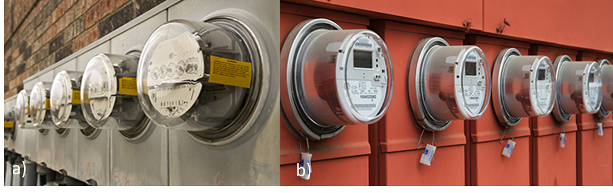
<그림 1> 기계식 전기계량기(a)와 e미터(b)
두 종류의 전기계량기는 모두 유효 전력량을 측정하지만, e미터는 기계식 전기계량기가 계산할 수 없는 전압, 전류, 전력, 무효 전력량, 주파수, 역률, 위상각 등의 파라미터를 추가적으로 계산할 수 있다.
이러한 파라미터는 전력 품질, 정전, 로드 밸런싱 및 탬퍼링을 나타내므로 에너지 소비자와 유틸리티 공급자에게 매우 통찰력 있는 정보를 제공한다.
e미터에서의 에너지 측정은 주로 소비자에게 요금을 청구하고 부하 조건을 식별하며 고장을 모니터링하는 데 사용된다.
그러나 에너지 절약, 스마트 시티, 부하 분리의 중요성이 강조되면서 서브 미터, 스마트 플러그, 서버 전력 모니터, 보호 릴레이, 고장 표시장치 및 회로 차단기를 포함한 많은 장비들이 정확한 에너지 측정을 필요로 하게 되었다.
가령 오늘날의 스마트 기기는 효율과 제어 능력을 향상시킬 수 있는 임베디드 미터링과 무선 커넥티비티를 포함하고 있다. 주택 소유자나 기업 소유자는 이러한 종류의 기기를 원격으로 모니터링하고 관리해 에너지를 절약한다.
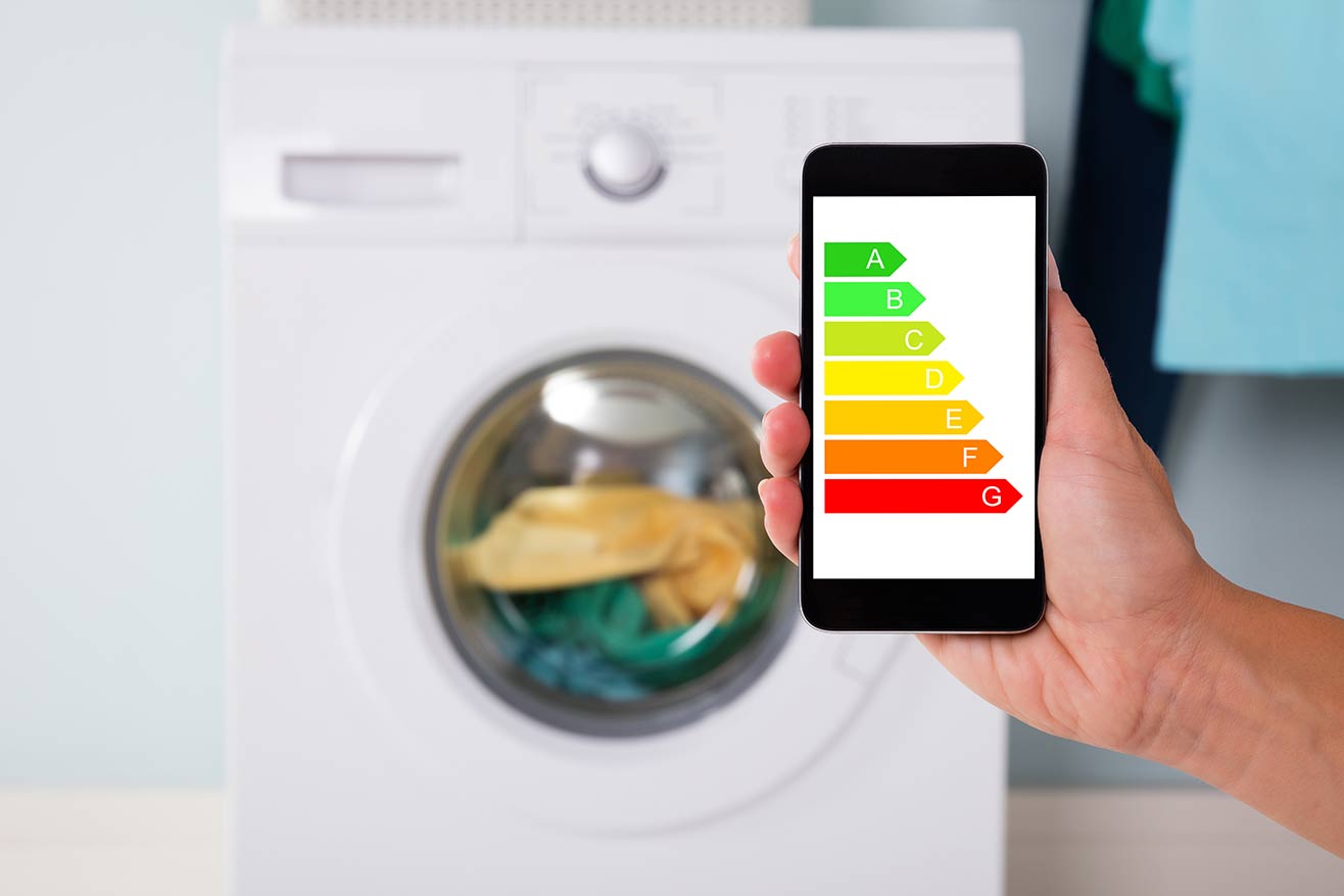
<그림 2> 임베디드 미터링 기능을 이용하는 스마트 기기의 전력 소모 보기 예제

스마트 기기는 부하의 한 예에 지나지 않는다. 대부분의 부하와 소스는 단상, 2상, 3상 구성으로 분류할 수 있다. 대부분의 가정에서 단상 AC 주 전원은 주로 110V~230V 사이에서 중성 선을 기준으로 하는 한 종류의 전압을 제공한다.
부하에 의해 소비되는 전류는 직접적으로 사용되는 장비의 종류에 따라 달라지며, 전력은 AC 전압과 전류 곱의 순시 합이다. 시간의 흐름에 따른 전력을 평균화하면, 이는 전력량과 같다.
TI의 MSP430 마이크로컨트롤러 중 하나를 사용하면 전력과 전력량을 쉽게 계산할 수 있다. MSP430F67xxA 및 MSP430i20xx MCU는 24비트 시그마-델타 아날로그-디지털 컨버터 및 AC 파형을 캡처하고 처리하여 전력, 전력량과 다른 파라미터를 계산하는 기타 통합 아날로그 및 디지털 모듈을 포함한다.
임베디드 미터링 애플리케이션을 설계하는 엔지니어는 MCU를 사용하고 알고리듬을 개발하거나 복잡한 신호를 처리하면서 경험이 제한적일 수 있다.
하드웨어의 설계 과제는 선택된 전압 및 전류 센서 유형에 대한 아날로그 프론트 엔드 회로를 구현하는 것을 포함한다. 소프트웨어의 설계 과제는 MCU의 모듈을 구성하고 동기화하며, 포괄적인 일련의 정확하고 안정적인 결과를 얻기 위해 계산을 최적화하는 작업을 포함한다.
시스템 레벨의 설계 과제는 가장 어려운 과제일 수 있는데, 모든 것을 통합하고, 보정을 구현하고 수행하며, 단일 및 다상 구성에 걸쳐 MCU 간 마이그레이션을 포함할 수 있다.
그림 3은 이러한 임베디드 미터링 설계를 단순화, 자동화, 가속화하기 위해 TI가 개발한 에너지 측정 디자인 센터(Energy Measurement Design Center, EMDC) 그래픽 사용자 인터페이스(GUI)와 소프트웨어 라이브러리다.
이제 엔지니어는 임베디드 미터링 기능을 구현하는 데 필요한 모든 것을 개발하는 대신, EMDC를 사용하면서 무선 커넥티비티와 같은 다른 기능을 개발하는 데 집중할 수 있다. 실제로도 설계 시간을 몇 개월에서 며칠로 단축할 수 있다.
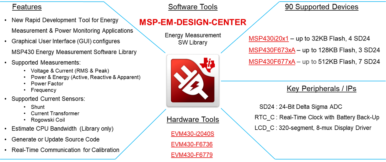
<그림 3> EMDC 개요
그림 4는 임베디드 미터링 시스템의 세 가지 주요 구성요소를 보여준다.
첫째, 고전압 소스는 정확한 테스트 장비 또는 AC 주 전원이 될 수 있다. 다음으로, 시스템은 MCU와 센서를 포함하는 평가 모듈 또는 커스텀 보드가 될 수 있다. 마지막으로, GUI 또는 호스트 MCU는 시스템의 MCU를 제어하고 통신한다.
여기서 EMDC GUI는 소프트웨어 라이브러리를 구성하면서 CPU 대역폭을 추정하고, 구성 오류 검사, MCU를 위한 소스 코드 생성, 시스템 보정을 수행하고 결과를 표시한다. 이 모든 것이 한 줄의 코드도 작성할 필요 없이 실행된다.
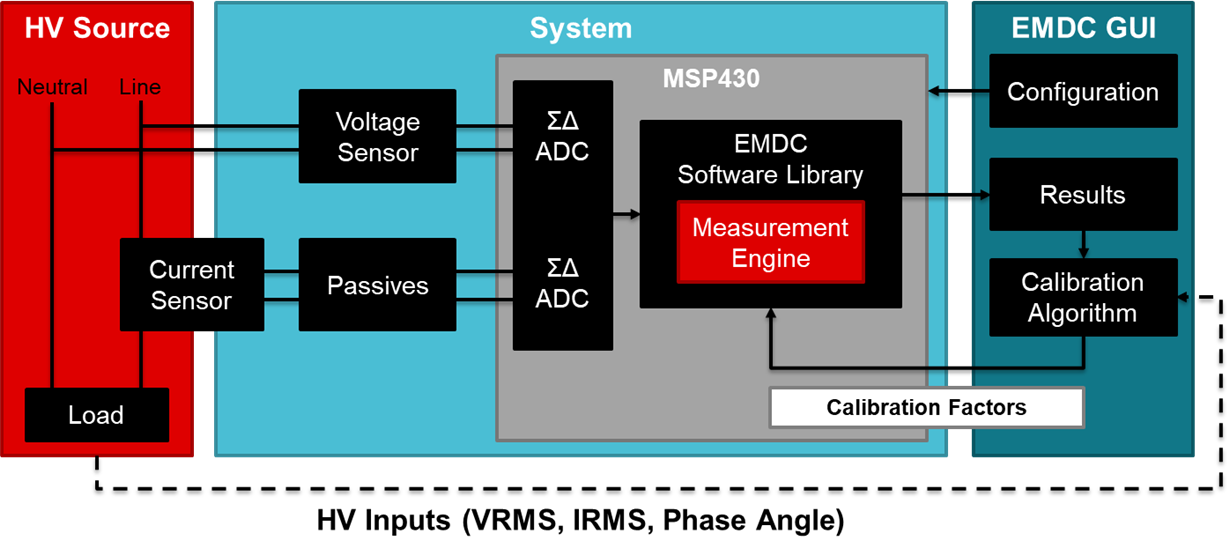
<그림 4> 단상 구성을 위한 임베디드 미터링 시스템 블록 다이어그램
그림 5에 보이는 EMDC GUI 내에는 MCU와 센서를 나타내는 아이콘이 있으며, 이 아이콘들은 시스템 구성에 따라 사용자가 드래그 앤 드롭 할 수 있다. 또한, 드롭다운 메뉴를 이용해 지원되는 MCU 간에 마이그레이션 할 수 있다.
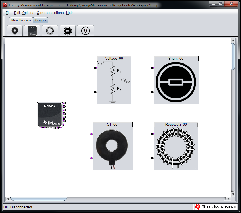
<그림 5> MCU 및 센서 아이콘이 있는 EMDC GUI
이 무료 툴을 설계 시 사용하는 방법에 관한 자세한 내용은 EMDC GUI 및 소프트웨어 라이브러리를 다운로드하고 설치 조건 및 지원되는 평가 모듈에 대해 알아보거나 사전 구성 및 사전 보정된 프로젝트, 관련 바이너리 이미지를 참고하면 된다.
또 설계가 유사한 경우 이 EMDC 프로젝트를 수정하거나, 다른 경우에는 새로운 프로젝트를 시작할 수 있다.
본 기사는 텍사스 인스트루먼트의 엔지니어 제임스 에반스(James Evans)의 글을 정리한 것입니다.
Comments
Related news
Cognex Launches Insight 9902L, Embedded Industrial Line Scan System
Cognex has launched the Insight 9902L, a line scan vision system. The Insight 9902L is a high-resolution vision system and an embedded industrial line scan system that processes images directly from the camera. It is particularly well-suited for detailed inspection of large or cylindrical objects on fast-moving production lines.
2018.11.01by 이수민 기자
Microchip Unveils "PolarFire SoC Architecture" for Running Real-Time Embedded Applications
Microchip Technology has expanded its Mi-V ecosystem through its subsidiary Microsemi Corporation by launching a SoC FPGA architecture that combines the PolarFire FPGA product family with a royalty-free, open RISC-V ISA-based microprocessor subsystem. Through the PolarFire SoC architecture, developers can execute deterministic real-time embedded applications with various operating systems for diverse temperature and space-constrained applications in networked collaborative IoT systems.
2018.12.11by 이수민 기자
.jpg)
Kuntek to distribute Imperas' RISC-V software development tool riscvOVPsim for free
Quntech will distribute riscvOVPsim, a virtual machine that supports software development for Imperas' open-source CPU RISC-V, free of charge to domestic developers. Imperas' riscvOVPsim is a virtual machine for embedded software development projects running on RISC-V environments. riscvOVPsim is a RISC-V ISS (Instruction Set Simulator) that supports initial implementation testing and design verification of RISC-V CPU core designs. riscvOVPsim can be downloaded from GitHub.
2018.12.12by 이수민 기자
Korea Instrument, KOLAS Accredited Calibration Agency First to Simultaneously Acquire ISO/IEC 27,001·27,701
Korea Instrument has become the first among KOLAS accredited calibration agencies to simultaneously acquire ISO/IEC 27,001 and ISO/IEC 27,701 certifications. Through its proprietary platforms CWIZ Enterprise and CWIZ Partners, the company has embedded information security and personal data protection requirements across all business processes including customer information, equipment data, and calibration reports, with plans to continuously advance its management system through regular audits and security inspections.
2026.10.12by 배종인 기자

TeamViewer One, IT Incident Automation Workflow and Resolution Center Enhanced
TeamViewer has added IT incident automation capabilities and an advanced Resolution Center to its integrated digital workplace management platform 'TeamViewer ONE'. Recurrent service disruptions, configuration errors, and capacity shortages are automatically handled according to preset policies, and device status verification through script deployment can be managed in a unified interface, significantly reducing repetitive tasks for IT teams.
2026.10.12by 배종인 기자











