



Improving Electric Vehicle Efficiency Depends on Powertrain System Integration
 Published2021.06.24 16:24
파워트레인 통합, 표준화와 모듈화로 설계 간소화
동일한 정격 전압의 자기 부품 통합 달성 가능해
더 적은 부품으로 더 많은 기능을 수행하는 차량용 애플리케이션은 차량의 무게와 비용을 줄이고 안정성을 높인다. 전기차(EV)나 하이브리드 전기차(HEV)의 설계를 통합하려는 이유다. 파워트레인 통합은 온보드 충전기(OBC), 고전압 DC/DC, 인버터 및 전력 분배 장치(PDU) 같은 파워트레인 최종 장치들의 통합을 의미하는데, 그림 1처럼 기계적, 제어 또는 파워트레인 수준에 적용할 수 있다.
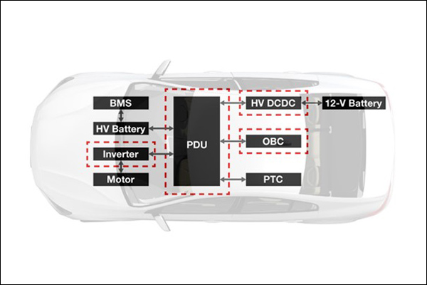
그렇다면 왜 파워트레인 통합은 HEV/EV에 유용할까? 파워트레인 최종 장치 구성 요소들을 통합하면 전력 밀도와 신뢰성을 높일 수 있으며, 비용도 줄일 수 있다. 더불어 표준화와 모듈화가 가능해 설계와 조립을 간소화한다.
.jpg)
파워트레인 통합에는 많은 방법이 있는데, 그림 2는 파워트레인, 제어 회로, 기계장치를 결합할 때 높은 전력 밀도를 달성하는 4가지의 일반적인 접근방법을 OBC와 DC/DC의 통합을 예시로 들어서 설명하는 것이다.
△옵션 1은 독립적인 시스템을 사용하는 방법이다. 이 방법은 몇 년 전만큼 오늘날 그리 인기 있지 않다. △옵션 2는 두 단계로 나눌 수 있다. DC/DC 컨버터와 OBC의 기계적 하우징은 공유하나 독립적인 쿨링 시스템은 분리하거나, 혹은 하우징과 쿨링 시스템을 둘 다 공유하거나다. 후자가 가장 일반적인 선택이다.
이어서 △옵션 3은 제어 스테이지를 통합하는 방법이다. 이 방법은 옵션 4로 발전하고 있다. △옵션 4는 전력 회로에 필요한 전력 스위치와 자기 부품이 더 적기 때문에 비용 우위가 가장 높지만, 제어 알고리즘이 가장 복잡하다.
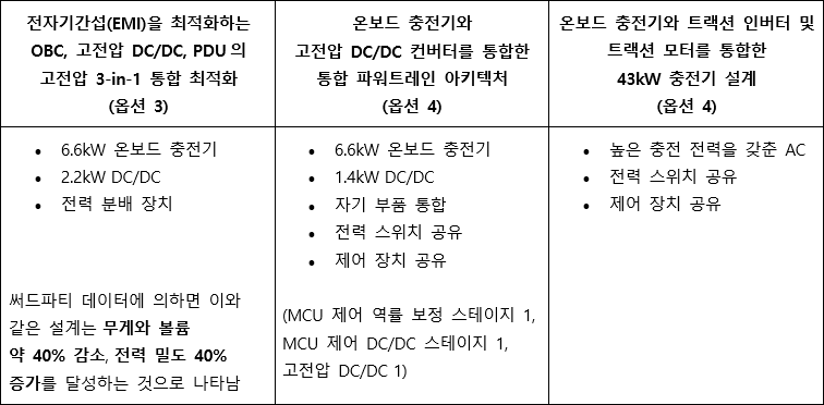

표 1은 현재 시중에 사용 중인 콤보박스 아키텍처를 간략히 설명한 것이다.
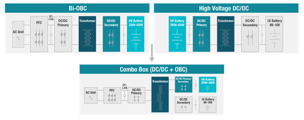
그림 3은 전력 스위치를 공유하고 자기 부품을 통합한 파워트레인 블록 다이어그램이다. OBC와 고전압 DC/DC 컨버터는 둘 다 고전압 배터리에 연결되므로 온보드 충전기와 고전압 DC/DC에 대한 풀브리지 정격 전압은 같다. 따라서 온보드 충전기와 고전압 DC/DC에 대해 풀브리지와 전력 스위치를 공유할 수 있다.
이 밖에도 2개의 트랜스포머를 통합하여 자기 부품 통합도 달성할 수 있다. 이는 이들 부품이 고전압 측에 동일한 정격 전압을 갖기 때문에 가능한 것으로, 최종적으로 3로(three-terminal) 트랜스포머가 된다.
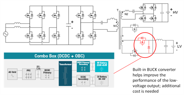
그림 4는 저전압 출력의 성능을 높이기 위해 벅 컨버터를 어떻게 내장하는지 보여준다. 이 통합 토폴로지가 고전압 배터리 충전 조건에서 동작할 때, 고전압 출력은 정확하게 제어된다. 그러나 트랜스포머의 2개 터미널이 결합하기 때문에 저전압 출력의 성능은 제한된다. 저전압 출력 성능을 높이는 방법은 빌트인 스텝다운 컨버터를 추가하는 것이다. 하지만 이 방법은 추가적인 비용이 수반된다.
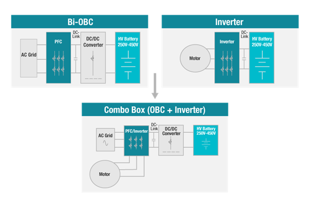
OBC와 고전압 DC/DC 통합과 마찬가지로 온보드 충전기와 3개 하프 브리지에서 역률 보정 스테이지의 전압 정격은 매우 근접한다. 따라서 그림 5 같이 최종 장치 구성요소 2개에 의해 공유되는 3개 하프 브리지와 전력 스위치 공유가 가능해 비용을 낮추고 전력 밀도를 높일 수 있다. 모터에는 보통 3개의 권선이 있으므로 OBC에서 역률 보정 인덕터로 권선을 공유해 자기 부품 통합을 달성할 수 있다.
◇ 유연성, 파워트레인 통합의 핵심
낮은 수준의 기계적 통합에서부터 높은 수준의 전자적 통합까지 통합의 진화가 계속되고 있다. 유연성은 파워트레인 통합의 핵심으로, 엔지니어는 4가지 이상의 다양한 옵션을 사용해 어느 수준에서나 위에서 언급한 설계를 검토할 수 있다.
한편, 다양한 아키텍처를 단일 시스템에 적용하려는 엔지니어는 △최고 성능을 달성하기 위해서는 신중한 자기 부품 통합 설계가 필요하며, △제어 알고리즘은 통합 시스템에서 더 복잡해질 것이며, △더욱 작은 시스템 내의 모든 열을 흩어지게 할 수 있는 고효율 쿨링 시스템 설계가 요구된다는 사실을 유념해야 할 것이다.
이 기사는 TI 상하이 CFT 팀의 웨이지 차오(Weijie Cao) 엔지니어가 저술한 '파워트레인 시스템 통합을 통해 전기차 비용 절감 및 주행거리 개선(Reduce EV cost and improve drive range by integrating powertrain systems)'이란 제목의 글을 정리한 것입니다.
Comments
Related news
LG Electronics Seeks Automotive Sales Channels by Establishing Joint Venture with Magna
LG Electronics has decided to establish a joint venture with Magna International, a Canadian automotive parts supplier ranked third globally by revenue, in the electric vehicle (EV) powertrain sector. Considering the rapid advancement of vehicle electrification trends worldwide, both companies are pursuing this partnership to build mass production systems early and enhance business competitiveness and growth potential.
2020.12.25by 명세환 기자
TI Announces Integrated Solutions for Electric Vehicle Powertrain Systems
The performance of electric vehicles is determined by the power efficiency and size of the powertrain. In response, Texas Instruments has announced an integrated powertrain system solution that enhances the economics and affordability of hybrid and pure electric vehicles while extending driving range.
2021.06.03by 이수민 기자
Keysight Launches EV and EVSE Charger Test Solutions
The increasing complexity of the grid and innovation are raising testing challenges for electric vehicles, electric vehicle supply equipment charging, and grid edge applications. In response, Keysight has launched the 'SL1200A Series Scienlab Regenerative Three-Phase AC Emulator'. The new emulator is a single-vendor solution comprising hardware, software, and services.
2021.06.21by 이수민 기자
[e4ds Tech Day 2026 ⑨] Sim Sang-gyu, Autocrypt CTO: "In the Physical AI Era, Automotive Security Must Extend Beyond the Vehicle"
At e4ds Tech Day 2026, Sim Sang-gyu, CTO of Autocrypt, explained automotive cybersecurity strategies in the era of Physical AI and SDV (Software-Defined Vehicle). Automobiles are evolving as part of an ecosystem connected to AI, cloud, chargers, IoT, and robots, and he emphasized that the scope of security must expand beyond the vehicle interior to the entire connected environment. In particular, AI model tampering, adversarial attacks, OTA updates, and EV charger hacking were identified as major threats. He explained that response measures require zero trust, AI model integrity protection, intrusion detection, Security by Design and Default, and full lifecycle security management, and that proactive security system establishment beyond regulatory compliance is critical for securing future mobility competitiveness.
2026.10.12by 배종인 기자

Practical HIL Construction Strategy for Automotive and Off-Highway Controller Validation
As vehicle E/E architecture transitions to zonal structures and shifts to software-defined vehicles (SDV), the number of controllers (ECUs) requiring validation and software complexity are surging dramatically. Meanwhile, real vehicle testing cannot provide repeated verification under identical conditions and entails lead time and safety concerns. This white paper explains the principles of HIL (Hardware-in-the-Loop) validation and the structure of the NI platform composed of PXI, SLSC, and VeriStand, and through two actual implementation cases—Camera Record & Replay HIL for In-Cabin Monitoring Controller (ICMU) and Forklift Controller (VCU) HILS—describes how controller-level regression testing becomes possible. Additionally, it explicitly states application boundaries and limitations, such as lack of A2B support.
2026.10.12by 편집부











